Tool Manufacture
Die Design / Forming Simulation
Stamping simulation software is used to test the forming process to ensure that complex metal forming problems can be identified as early as possible during tool development. The outcome of the forming process and part formability must be simulated with realistic values to guarantee that a perfect 3D-Die-Layout is developed during tool design. If input parameters such as material characteristic values are inaccurate, the simulation will produce poor forming tools. GOM systems deliver precise material characteristic values (FLC/FLD) to support the stamping simulation software. Once the right values are input, forming tools can be produced more cost-effectively and the first prototypes produced faster.

Reduction of Machining Times
When the part and tool design for a product has been approved by the forming simulations within CAD programs and an appropriate material has been chosen, the next step is to CNC machine a stamping die/tool from a cast blank.
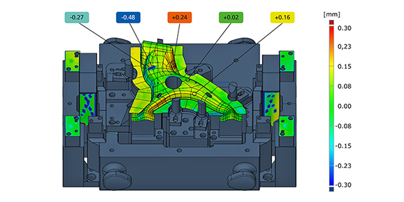
This process can be speeded up significantly by 3D digitizing the cast blank with GOM’s ATOS system. Thus, interference contours such as sprues can be recognized promptly and collisions with the milling cutter avoided. The digitized cast data is then used to align the cast blank with the CAD model in order to verify the machining allowance for the entire part and position it correctly on the CNC machining center. This generates optimum cutting paths, avoids “air milling” and reduces machining times by more than 50%.


